Motor Starter Control PLC Logic
In most industrial applications we generally find the PLC controlling motor starters. Starters are required for dc motors and induction motors to limit the starting current and protect the armature winging.
A universal motor (ac series motor) is used in this experiment. Although the above motor may be started directly from the rated voltage, it is required to start the motor with a resistor as shown in Figure (b). The starter resistor is to be shorted out after 8 seconds.
Motor Starter Control
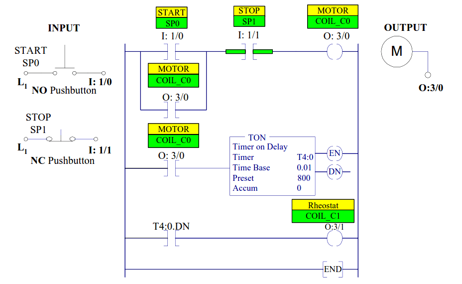
Figure a: Ladder program for the motor starter control
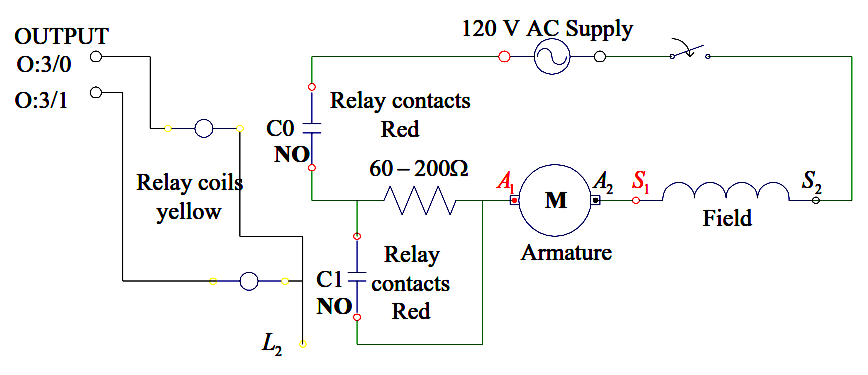
Figure b: Electric circuit for the motor starter control
PLC Logic Explanation
The ladder program is shown in Figure (a) is designed for the following sequential task:
1. Start pushbutton is pressed. Reference input SP0 (I:1/0) is closed, the output Coil_C0 (O:3/0) is energized. Contactor C0 closed and the motor starts with the resistance in the circuit.
2. Contact (O:3/0) across pushbutton closes sealing in the output Coil C0.
3. Contact (O:3/0) in the second rung closes and the timer is energized.
4. After 8 seconds TMR is enabled closing the timer contact (T4:0.DN) in the third rung. This will energize output Coil_C1 at (O:3/1). The contactor C1 across the resistor is closed, shorting out the resistor.
5. The stop pushbutton SP1 stops the motor releasing the holding contact across the START contact.
Also Read: Star Delta Motor Starter
Author: Dr. Hadi Saadat


Responses