PLC Automation Basics: 4-20 mA Analog Signals for Beginners
About Course
In modern industrial plants, machines do not work in isolation. Sensors continuously measure pressure, temperature, flow, and level, while controllers make decisions based on those measurements. At the heart of this communication lies a simple yet powerful concept: the 4-20 mA analog current signal.
Despite rapid advancements in digital communication and fieldbus technologies, the 4-20 mA current loop continues to be the most trusted signal standard in industrial automation. From PLC-based control systems to field instrumentation installed kilometers away, this signal remains the backbone of reliable process control.
This online course is designed to help beginners clearly understand how and why 4-20 mA works, its role inside PLC systems, and the engineering history that made it the global standard.
Why 4-20 mA Matters in Industrial Automation?
Industrial environments are electrically noisy, physically harsh, and often spread across large areas. Signal transmission in such conditions must be accurate, stable, and immune to interference.
Voltage signals can easily degrade due to cable resistance, electromagnetic noise, induction voltages, or grounding issues. In contrast, a current-based signal maintains its integrity regardless of distance or minor wiring resistance. This is the primary reason industries worldwide rely on the 4–20 mA standard.
Learning this signal is not optional for anyone working in automation—it is foundational.
What Makes 4-20 mA Different from Other Signals?
One of the most common beginner questions is:
Why was 4–20 mA chosen instead of 0–10 V, 0–20 mA, or any other range?
The answer lies in engineering practicality:
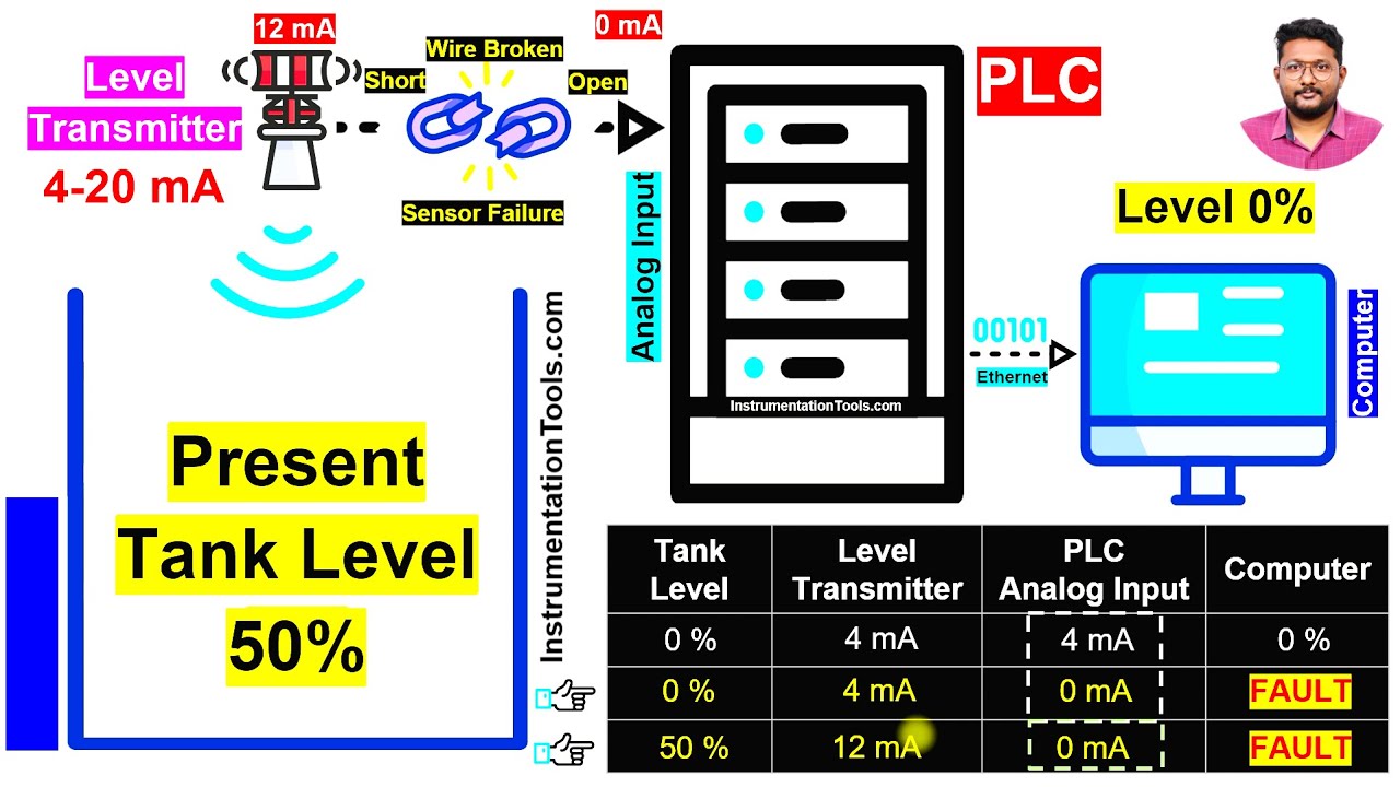
- 4 mA represents a live zero, not an absence of signal
- 0 mA indicates a fault, such as cable break or transmitter failure
- The current range supports long-distance transmission
- Field devices can often be powered directly from the loop
- Why 4mA? Why Not 5mA? Why exactly 4mA is selected?
- Why 20mA? Why Not 18 mA or 22mA? Why exactly 20mA is selected?
- The History of the Signals and Reasons behind the 4-20 mA range selection
This course explains these decisions step by step, without assumptions or shortcuts.
Course Focus and Learning Approach
This is a fundamentals-first course, designed especially for learners who want clarity instead of memorization.
You will learn not just what 4–20 mA is, but:
- Why it was designed this way
- How PLCs read and process it
- How it behaves in real industrial installations
Every concept is explained with practical reasons and explanations.
Key Topics Covered in the Course
Understanding the 4–20 mA Standard
Learn the complete reasoning behind the 4–20 mA range, including:
- Live zero vs dead zero
- Signal reliability and fault detection
- Why 20 mA was selected as the upper limit
PLC and Analog Signal Fundamentals
Understand how PLC systems handle analog signals:
- The basics of 4-20mA signals
- Analog input and output concepts
- Converting current signals to engineering values
Sensors, Transmitters, and Current Loops
Explore how field instruments generate and transmit 4–20 mA signals:
- Pressure, level, temperature, and flow transmitters
- Loop-powered devices
- Signal flow from field to control room
Advantages and Practical Limitations
This course does not present 4–20 mA as perfect—it presents it as practical:
- Noise immunity and long-distance stability
- Simple wiring and easy troubleshooting
- Limitations compared to modern digital protocols
Real-World Industrial Applications
See how 4–20 mA is actually used in plants:
- Tank level measurement
- Pump speed control
- PLC-based monitoring and control loops
Why Learning 4–20 mA is Still Relevant Today?
Even with technologies like Foundation Fieldbus, Profibus, HART, and Ethernet-based systems, most plants still depend on 4–20 mA signals for critical measurements. Why?
Because when systems must work 24×7 without failure, simplicity and reliability win.
Engineers who understand 4–20 mA deeply can:
- Diagnose loop problems faster
- Design more robust control systems
- Interface smart instruments confidently
- Work effectively across PLC, DCS, and hybrid systems
Who Should Take This Course?
This course is ideal for:
- Beginners starting with PLC and industrial automation
- Engineering students learning process control fundamentals
- Instrumentation and electrical technicians working with field signals
- PLC professionals strengthening analog signal basics
- Anyone curious about why 4–20 mA dominates industrial measurement
No prior advanced knowledge is required, everything is built from the ground up.
What You Will Gain by the End of the Course
By completing this course, you will:
- The historical reasons for the selection of 4 mA and 20 mA
- Clearly understand how 4–20 mA current loops work
- Know why this standard is used globally
- Understand how PLCs read and use analog signals
- Be able to relate theory to real industrial scenarios
- Build a strong foundation for advanced automation topics
Course Access and Certificate
- Most of the course content is available free of charge
- YouTube Channel Membership is required to unlock selected exclusive lessons
- Membership is also needed to receive the official course completion certificate
Final Thoughts
The 4–20 mA signal may look simple on paper, but it represents decades of engineering experience and practical decision-making. Mastering this concept is a crucial step for anyone serious about industrial automation and instrumentation.
PLC Automation Basics: 4–20 mA Analog Signals for Beginners is your guided entry into this essential topic, clear, practical, and industry-focused.
If you want to truly understand how machines talk to controllers, this is where your journey should begin.
Course Content
Basics of PLC Automation Systems
-
Course Guidelines
-
06:54
-
Control Room: Operator Interface Graphics
06:22 -
Introduction to 4-20 mA Analog Signals
06:44 -
05:35
-
Practical Industrial Example of 4–20 mA Current Loop
08:02 -
The PLC Analog Input Signals
08:00 -
Pump Speed Control Example in PLC with 4–20 mA Signals
08:39 -
The PLC Analog Output Signals
04:21 -
Basic Questions on 4–20 mA Current
03:03 -
Basic Knowledge Quiz
Basic Concepts of PLC Analog Signals
History of Control Systems
Why is 4 mA Used as the Reference Standard?
Why 20 mA Is Selected for 4–20 mA Signals?
4-20 mA Analog Signals Standard
Key Facts
Advantages of 4-20 mA Analog Signals
Disadvantages of 4-20 mA Analog Signals
Course Wrap-Up
Student Ratings & Reviews
Thanks for providing details of this topic.