A Simple Ladder Diagram with NO and NC Contacts
The below figure illustrates an example of a simple ladder program with the NO and NC contacts driving an output rung.
Ladder Diagram with NO and NC Contacts
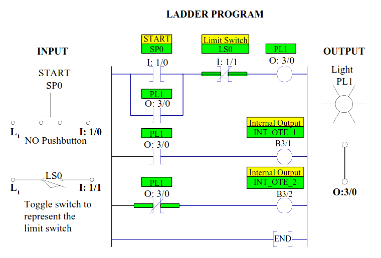
With the limit switch LS0 open, when SP0 is pushed the reference input SP0 (I: 1/0) is closed, the output coil PL1 (O: 3/0) is energized closing all (O: 3/0) contacts and the pilot light PL1 will be lit.
Control contact (O: 3/0) in parallel with contact I: 1/0 then closes sealing in the output coil PL1 even if the start button is released.
Since output PL1 (O: 3/0) is ON, the normally open contact (O: 3/0) in the second rung will close, turning the internal output coil INT_OTE_1 (B3/1) ON.
The NC contacts (O: 3/0) in the third rung will open because the examine for an OFF condition is not true (reference output is ON), therefore turning internal output INT_OTE_2 (B3/2) OFF.
Note that outputs B3/1 and B3/2 will not turn a real output device ON because these internal bits are not mapped to the output device.
When the limit switch LS0 is closed the NC contact LS0 (I: 1/1) in the first rung opens, the output O: 3/0 is de-energized, and the pilot light PL1 is turned off.
The normally open contact (O :3/0) in the second rung will open, turning the internal output coil INT_OTE_1 (B3/1) OFF.
The NC contact in the third rung is closed turning the internal output coil (INT_OTE_2), B3/2 ON.
Author: Dr. Hadi Saadat
Read Next:


good lession
Great ???? programmable ladder logic.