Traffic Light Control using PLC Ladder Logic Programming
Design ladder logic for 4 way-traffic light control system
The traffic light is one of the classic examples in PLC ladder logic.
We can take four directions (North, South, west, and east) with three output lamps (Green, Red, and Yellow).
You can build your own concept for making logic for this example.
Follow below tabular column – Logic for the four way traffic light
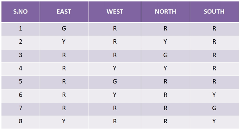
List of Inputs and Outputs
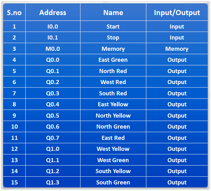
Traffic Light Control using PLC
Logic Explanation
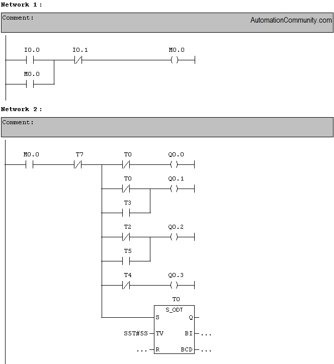
Network 1
Latching rung to operate the system through Master Start and Stop PB.
Network 2
Starting the timer to turn on output East Green, North-South-West is in red. Parallel circuits are added to turn ON/OFF the output in up next sequence.
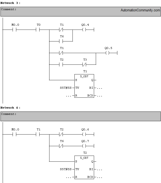
Network 3
Turning on North Yellow and East Yellow. Parallel circuits are added to turn ON/OFF the output in up next sequence.
Network 4
Turn on East Red and North Green.
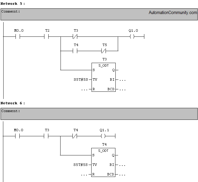
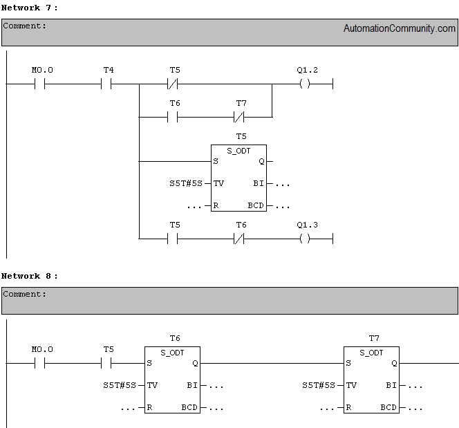
Network 5, 6, and 7
Same procedures followed to turn on further outputs.( Refer Tabular column for sequence of operation)
Network 8
Timer 7 (T7) done bit is used to restart the cycle from beginning
Program runs continuously until STOP PB is pressed
Time delay of 5s has given using timers which will make each cycle with 5s delay.
Author: Hema
Training Course: Siemens PLC Training


Thank You.
Very helpful, thank you very much
This illustration was very helpful. From it, I also learned that there is more than one way to obtain a desired result.
Thank you so much
This is great, thank you.
I learned the logic and from it I am being able to design a different logic.
It is helpful and I am so excited, therefore I cannot wait to gladly take another lesson and become a programmer.
Thanks.
could you explain me the logic i would very glad to learn it
I have a doubt in Network 2 and 8.
After the Timer T7 in Network 8 runs for 5 seconds, won’t the N/C contact of T7 in Network 2 become open ? If it opens how will output coil Q0.0 and Q0.1 will get energized? Thus, how reset action will occur ?
Kindly clarify my doubt.
1) I have doubt in n/w 2 Q0.1(North-red) line..we have connected parallel Ncc T0 with T3. in this prob, shount’t be OCC T7 along with NCC T4 ,instead of T3 (as Northen red will be red after T4 and remains till T7 )??
2) in same n/w , Q0.2(west-red), you have connected Ncc T2 parallel with Occ T5,, shoun’t it be occ T6 in series with Ncc T7,,instead of occ T5???
I have these doubts….I hope u have understood what i’m tryinbg to sya
I be waiting for doubt clearification. Thank you
it was clear explanation and am so excited .thank you very much
Superb
Thanks
Nice
Thank you
sir,
Logic Explanation should be immediate after network no.
Good explanation
very informative
Hi I’m new this course please explain detials me
Very helpful thank you
how thank for clear explanation
Thank you mam
Thank you
Thank you
Thank you
Thank You
Good explanation
thanks
thank tou
Thank you mam
Kindly make some easy process
Like as an identified timer
Thank you
Great, helpful
Nice
Can you help me copy word like 0000 0000 0000 11111 to memory M0 to M15 and then delay and copy another copy anather word to the same memory bits? Especially in ispsoft
this is deeply understable and very good solution
i will test it on my PLC
got it.
thanks you nice info
Thank you for valuable teaching
Thank you
helpfull
very informative
THANK YOU