Ladder Diagrams
The logic implemented in PLCs is based on the three basic logic functions (AND, OR, NOT). These functions are used either singly or in combinations to form instructions that will determine if a device is to be switched ON or OFF.
The most widely used languages for implementing ON/OFF control and sequencing are ladder diagrams. It is easy to understand, and most plant or industrial electricians are accustomed to working with elementary relay diagrams.
Since this type of instruction set is composed of contact symbols, it is also referred to as contact symbology. The ladder circuit connections in the PLC are implemented via software instructions. All the logical wiring can be thought of as being inside the CPU (soft-wired as opposed to hardwired).
The complete ladder diagram can be thought of as being formed by individual circuits, each circuit having one output. Each of these circuits is known as a rung.
Therefore, a rung is the contact symbology required to control an output in the PLC. A complete PLC ladder diagram program then consists of several rungs, each controlling an output interface which is connected to an output field device as shown in the below Figure.
Ladder Diagrams
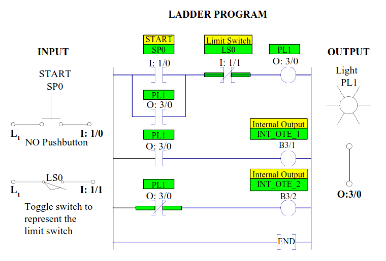
Each rung is a combination of input conditions (symbols) connected from left to right between two vertical lines, with the symbol that represents the output at the far right.
The symbols that represent the inputs are connected in series, parallel or some combination to obtain the desired logic; these input symbols represent the input devices that are connected to the PLC’s input interfaces.
When activated, these devices either allow current to follow through the circuit or cause a break in current flow, thereby switching a device ON or OFF. The input symbols on a ladder rung can represent signals generated from connected input devices, connected output devices, or from outputs internal to the controller.
In general, PLC architecture is modular and flexible, allowing hardware and software elements to expand as the application requirements change. A PLC eliminates hardwired control in favor of programmable control.
Once installed, the control plan can be manually or automatically altered to meet the day-to-day control requirements without changing the field wiring.
Contact Symbol
Programmable controller contacts and relay contacts operate in a very similar fashion.
For example, the control relay CR shown in the below Figure has two sets of contacts, one normally open (CR1) and one normally closed (CR2).
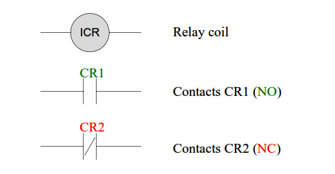
Figure: Relay Symbol with NO and NC contacts
If relay coil CR is not energized, contact CR1 will remain open and contact CR2 will remain closed. Conversely, if coil CR is energized, or turned ON, contact CR1 will close and contact CR2 will open.
The following symbols are some of the basic bit instructions used to translate relay control logic to contact symbolic logic.
Definition and Symbol Interpretation
Examine if Closed Instruction:
———-] [———
XIC Instruction
Generally referred to as normally open (NO) instruction. Typically represents any input to the control logic.
The input can be a real world input from a connected switch or pushbutton, a contact from a connected output, or a contact from an internal output.
The status bit is examined for an ON condition. If the status bit is “1”, then the instruction is TRUE. If the status bit is “0”, then the instruction is FALSE.
Examine if Open Instruction:
———-]/[———
XIO Instruction
Generally referred to as normally closed (NC) instruction. Typically represents any input to the control logic.
The input can be a connected switch or pushbutton etc., a contact from a connected output, or a contact from an internal output.
The status bit is examined for an OFF condition. If the status bit is “0”, then the instruction is TRUE. If the status bit is “1”, then the instruction is FALSE.
Output Energized:
———( )——–
OTE Instruction
Typically represents any output that is controlled by some combination of input logic. An output can be a connected device or an internal output (internal relay).
If the left-to-right path of input instructions in the rung is TRUE (all contacts closed), the output is energized (turned ON). If the rung is false, the output is reset to OFF.
Latch Output Coil:
———( L )——–
OTL Instruction
An electromagnetic latching relay function can be programmed on a PLC to work like its real-world counterparts.
This instruction is programmed if an output is to remain energized, even though the coil is energized only momentarily.
The output is turned ON and remains ON until it is unlatched by an unlatch output instruction of the same reference address.
Unlatch Output Coil:
———( U )——–
OTU Instruction
This instruction is programmed to reset a latched output having the same reference output. If any rung path has logic continuity, the reference address coil is turned off or unlatched to an off condition.
Author: Dr. Hadi Saadat


Thanks automation community
Here all videos is very helpful