Timers and Counters
Timers and counters are internal instructions that provide the same functions as timing relays and counters. They are used to activate or de-activate a device after a preset interval of time.
Timers and Counters
The timer is assigned an address as well as being identified as a timer. Also included, as part of the timer instruction is the time base of the timer, the timer’s preset value, and the accumulated value.
The timer instructions include:
Timer On-Delay (TON)
This instruction is programmed to provide time delay action. Once the rung has continuity, the timer begins counting time-based intervals and times until the accumulated value equals the preset value.
When the accumulated time equals the preset time, the output is energized, and the timed output contact associated with the output is closed. The timed contact can be used throughout the program as an NO or NC contact.
The accumulated value is reset when rung condition goes false.
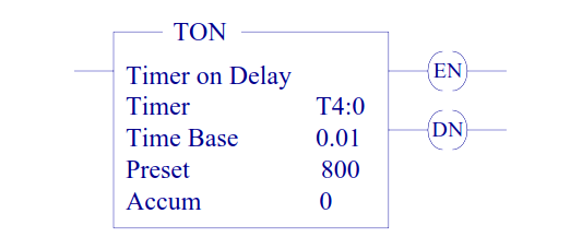
For SLC-500 processor the time base can be selected as 0.01 sec or 1.0 sec.
The control word uses three control bits:
Enable (EN) bit
The enable bit (EN) is set when rung conditions are true; it is reset when the rung condition becomes false.
Done (DN) bit
The done bit (DN) is set when the accumulated value is equal to the preset value. It is reset when rung condition becomes false.
Timer-timing (TT) bit
The Timer-timing bit (TT) is true when the timer is timing. When the timer is not timing the TT bit is false.
Timer Off-Delay (TOF)
This instruction is programmed to provide time delay action. If the rung does not have continuity, the timer begins counting time-based intervals and times until the accumulated value equals the preset value.
When the accumulated time equals the preset time, the output is energized, and the timed output contact associated with the output is closed. The timed contact can be used throughout the program as an NO or NC contact.
The accumulated value is reset when rung condition goes true.
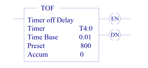
The done bit (DN) is set when the accumulated value is equal to the preset value. It is reset when rung condition becomes true. The enable bit (EN) is set when rung conditions are true; it is reset when the rung condition becomes false.
Counters
Counters are similar to timers, except that they do not operate on an internal clock, but are dependent upon external or program sources for counting. The counter is assigned an address as well as being identified as a counter.
Also included, as part of the counter instruction is the counter’s preset value as well as the current accumulated count for the counter. There are two basic types of counters, one that counts up and another one that can count down.
Count Up (CTU) and Count Down (CTD)
The up-counter output instruction will increment by one and the down-counter output instruction will decrement by one each time the counted event occurs.
These events could be caused by the number parts traveling past a detector or a limit switch. When the accumulated counts equal the preset count, the output is energized, and the counter output is closed.
The counter contact can be used throughout the program as an NO or NC contact

The done bit (DN) is set and remains set when the accumulated value is equal to the preset value. It is reset when rung condition becomes true.
The count up enable bit (CU) or the count down enable is set when rung conditions are true; it is reset when the rung condition becomes false or the appropriate reset instruction is enabled.
Counter and Timer Reset (RES)
The [RES] instruction is used to reset the timing and counting instruction accumulated values. A rung containing an NO or an NC contact together with the [RES] instruction is used.
The [RES] instruction must be given the same reference address as the related timer or counter. When the [RES] instruction is enabled, the counter accumulated value is reset.
Author: Dr. Hadi Saadat
Read Next:

Responses