Write Ladder Logic for the Simple Program
Write ladder logic for the simple ON/OFF of motor and lamp.
When
- Switch S1 and Switch S2 ON —– Motor 1 ON
- Switch S3 or Switch S4 ON —— Lamp 1 ON & Motor 1 OFF
- Switch S5 ON —– Lamp 1 OFF & Motor 1 ON again
When S1 and S2 ON Both are In ON Condition) should make Motor 1 should go ON.
When S3 or S4 (Anyone ON) will make lamp 1 ON and Motor 1 (Which was already turned ON by S1) to go OFF.
When S5 ON, lamp 1 (Which was already turned ON by S3 or S4) should go OFF and Motor 1 again ON (Which was already turned OFF by S3 or S4).
Ladder Logic Program
Logic Explanation
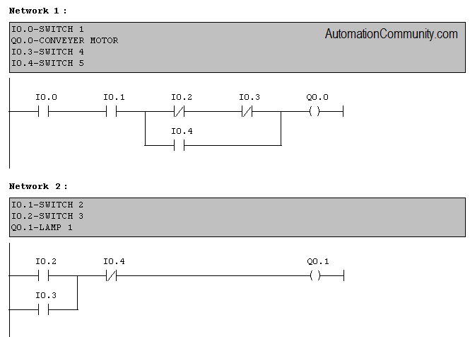
Network 1:
When switch 1 and switch 2 are pressed, the motor will turn on. Switch 3 and 4 are connected as normally closed contact in series with the output which will make output to go off when anyone goes ON.
Switch 5 is connected as normally open contact in parallel to turn ON motor again.
Network 2:
Switch 2 and 3 are connected as normally open contact in parallel with the output which will make output lamp 1 to go ON if anyone is ON.
Switch 5 is connected as normally closed contact to break the power line when switch 5 goes ON.
Author: Hema
Training Course: Siemens PLC Training


Good
The circuit is correct with the use of the five switches, I think it’s still possible to make use of more than two outputs.
But to limit the cost the circuit was design as simple as it is.
Thanks Tutor Hema
nice
simple and cool
yes
super mam
Good
It is nice
Good
using function block we can do some more simple ladder
Good nice
nice
Nice
Simple
nice
Nice
Nice
good
Good Explanation easy
The logic is well explained
Super mam
Very easy logic
Nice
simple cool & nice mam .
Good
good
companied problem with easy solution
ok
thanks
Plc programming
NICE
The ladder logic diagram controls a motor and lamps based on switch inputs. When Switch 1 is ON, the motor turns on. If Switch 4 or Switch 5 is ON, the motor turns off. Lamps 1 and 2 turn on when both Switch 2 and Switch 3 are ON, and they turn off when Switch 6 is ON. This logic ensures the desired control of the motor and lamps based on the switch states.
definitely informative
Nice !
GOOD
basic concept and and or and breaking