PLC Ladder Logic for simple ON-OFF of Motor and Lamp
Write ladder logic for the simple ON/OFF of motor and lamp.
Consider the following cases:
When
- Switch 1 ON —— conveyor motor ON
- Switch 2 and switch3 ON ——- lamp 1 ON & lamp2 ON
- Switch 4 or switch5 ON —– conveyor motor OFF
- Switch 6 ON —– lamp 1 OFF, lamp2 OFF
When you turn ON a switch 1 for the first time, conveyer motor should ON. When Switch 2 ON and switch 3 ON (Both are in ON Condition) should make Lamp 1 & 2 should go ON.
When Switch 4 or Switch 5 (Anyone ON) will make conveyor motor (Which was already turned ON by switch 1) should go OFF. When Switch 6 ON, will make lamps 1 & 2 (Which was already turned ON by switch 2 and switch 3) should go OFF.
Ladder Logic
Logic Explanation
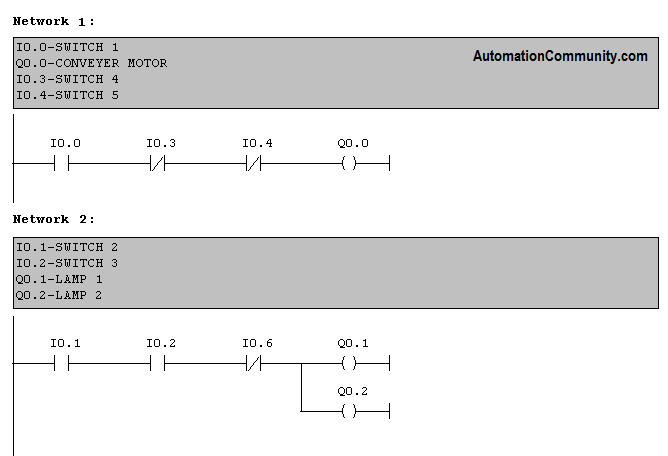
Network 1:
When switch 1 is pressed, the motor will turn on. Switch 4 and 5 are connected as normally closed contact in series with the output which will make output to go off when anyone goes ON.
Network 2:
Switch 2 and 3 are connected as normally open contact in series with the output which will make output lamp 1 and 2 to go ON only if both are ON. Switch 6 is connected as normally closed contact to break the power line when it goes ON.
Author: Hema
Training Course: Siemens PLC Training


Nice Info.
Perfect explanation
Good Explanation
Good Explanation
thanks for nice info
To my knowledge the circuit isn’t correct, for the fact that the Switch 4, Switch 5 and Switch 6 are already ON but the statement doesn’t say that.
The Conveyor Motor should be turned off when either the Switch 4 or 5 are ON, not when they are OFF, same thing for the Switch 6.
So I would rather do the following logic.
I connect I0.0 in series with M0. 2 to the output Q0.0 this is the first network and I0.0 turns ON the output Q0.0 the Conveyor Motor runs.
In the network 2
I connect I0.1 and I0.2 in parallel then both in series with M0.3 to the output Q0.1
Then the third rang I0.3 and I0.4 in parallel then these two switches supply the output Q0.2, then M0.2 will deactivate the Conveyor Motor in the first rung.
And finally I0.5 supplies Q0.3 in its turn will deactivate M0.3 in the rung 2.
Good ex.
Nice
good
Nice
Thanks Hema Mam for PLC Course….
And give good information and also u r teaching very awesome.
Thanks Hema mam. For this course. You are teaching awesome with very good explanation.
Great explanation
GREAT INFORMATION
Simple and correct way. Liked it
thanks
Thanks mam and clear explanation and good examples
Good Explanation
Thank you for your very good presentation.
Good explanation
nice
????????
Thanks
nice
Good explain
Easy understanding
Nice
Good
Easy learning
Good explanation
Good explanation inded
Nice
Good Explanation
Thank you good explanation
gained good knowledge
Nice explanation
good
Good Explanation Mam
nice information
Please any one update lader logic on time synchronization with plc timer control
GOOD
Nice Explanation
To my knowledge the circuit isn’t correct, for the fact that the Switch 4, Switch 5 and Switch 6 are already ON but the statement doesn’t say that.
The Conveyor Motor should be turned off when either the Switch 4 or 5 are ON, not when they are OFF
Good Explanations
Nice
great
right
when switch 1 is pressed the motor will turn on switch 4 and 5 are connected as normally closed contact in series with the output which will make output to go off when anyone goes on
NETWORK -2 Switch 2and 3 are conntected as normally open contact in series which will make output lamp 1 and 2 to go on only both are on .switch 6 is connected as normally closed contact to break the power line when it goes on
Good Explanation
Good teaching
good
Nice
good information
Nice superb
thank you
Nice program
Nice answer
Good explanation
Thank you
Latching on
good
very good explanation…….
very good & details clarification its really nice
this session was really vey good , thanks mam
Very good explanation
Good information
Good Explanation
I1: Switch 1 (Start Conveyor Motor)
I2: Switch 2
I3: Switch 3
I4: Switch 4
I5: Switch 5
I6: Switch 6
M1: Conveyor Motor
M2: Lamp 1
M3: Lamp 2
Here’s the ladder logic program description:
–[ ( )]–
| M1 |—————-( )————-( )————( )
| Motor | | | |
–[ ( )]– | | |
–[ ( )]– –[ ( )]–
–[ ( )]– | | |
| M2 |—————-( ) | |
| Lamp 1 | –[ ( )]– |
–[ ( )]– | |
| |
–[ ( )]– –[ ( )]– | |
| M3 |—————-( ) ( ) | |
| Lamp 2 | ( ) | |
–[ ( )]– ( ) | |
good info!!!
Nice information
Thanks
good explanation, it simple and contained more than one programing idea
Good information
nice info
EASY AND USEFUL CONTENT
FREE AND FRIENDLY INTERFACE
nice class and good explanation
I1: Switch 1 (Start Conveyor Motor)
I2: Switch 2
I3: Switch 3
I4: Switch 4
I5: Switch 5
I6: Switch 6
M1: Conveyor Motor
M2: Lamp 1
M3: Lamp 2
Here’s the ladder logic program description:
–[ ( )]–
| M1 |—————-( )————-( )————( )
| Motor | | | |
–[ ( )]– | | |
–[ ( )]– –[ ( )]–
–[ ( )]– | | |
| M2 |—————-( ) | |
| Lamp 1 | –[ ( )]– |
–[ ( )]– | |
| |
–[ ( )]– –[ ( )]– | |
| M3 |—————-( ) ( ) | |
| Lamp 2 | ( ) | |
–[ ( )]– ( )
Thanks
Great Information regarding PLC
best way like it
Nice
Good
nice info sir
Y
done
Nice information
Great information
Simple logic explanation
great session
My logic also correct
The course content is very good and helpful. The instructor way of explanation is also very fine and understandable.
Thanks ????
nice
Good explanations! thanks.
Thank you for Teaching Mam.
technically informative
Its useful
Nice explanation
WELL EXPLAINED
simple logic so help full
woo nice
Good explanation
thnks for nice information
I0.3 I0.4
—-|/|——|/|——————+——| |——( Q0.0 )
| I0.0
|
+——| |——
Q0.0
I0.5
—-|/|————————–+——| |——| |——( Q0.1 )
| I0.1 I0.2
|
+——| |——
Q0.1
I0.5
—-|/|————————–+——| |——| |——( Q0.2 )
| I0.1 I0.2
|
+——| |——
Q0.2