Gate Logic using PLC Program
Simulate the basic gate logic includes AND, OR, NOT combinational circuit using the Allen Bradley Programmable Logic Controller (PLC).
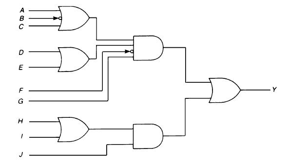
Write the ladder logic for the above shown logic diagram.
Gate Logic using PLC
PLC Program Description:
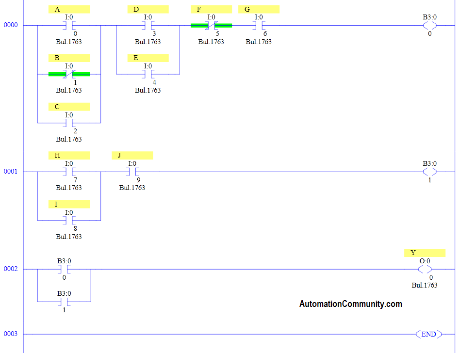
RUNG 000
A, C AND INVERTED B are into OR operation. D and E are into OR operation.
Those two results will make AND operation with G and inverted F. Final result is stored in memory coil B3:0/0.
RUNG 001
H and I are into OR operation and the result is AND with J.
Final result is stored in memory coil B3:0/1.
RUNG 002
B3:0/0 and B3:0/1 are into OR operation to enable or disable output Y.
Author: Hema
Training Course: Allen Bradley PLC Course


That’ great, the leader diagram is fine. The program is running.
It is just amazing to learn and be able to design a ladder diagram in various ways
The program works great. Looking forward to learning more.
I do it the same way. Thank you!
Nice
Imp
Nice
Nice
Nice
Nice1
Ok
Good
Nice
Great
Nice
Okkk
Great
very good and very nice
believe me is great
Awesome ????
It’s a ladder diagram for the logic gates
good
Work great!
PRACTICAL AND SIMPLE
Its working ?
Learning alot from this course.
Wowwww! I don’t know how to appreciate this course better, the learning process keep making me smile! Thanks Instructor, thanks for this course
good
THANK YOU FOR YOUR GUIDE FOR SUCH KIND OF LOGIC PROGRAMMING
I do it the same way by using memory bit
I am Easily understand
Very good teaching
ok..!
WITHOUT LOGIC NOBODY CAN OR IS VERY DIFFICULT TO CREATE A LOGIC PROGRAM . It sound confusing but we , me and my boy are learning this.. program run.
Its fun converting the logic gates into ladder logic.
That’s great leader diagram is fine
Practical And simple
So interesting logic ladder
good
Thank you so much 🤩🤩🤩🤩